Broadband Network access is a crucial element of all modern homes and business. And it’s a service that is constantly evolving.The main objtective of this evolution is to provide broadband solutions that are faster and more effective.
One of the most exciting developments in this area has been the concept of a passive optical Network(PON). Fibre optic technology is at the heart of PON and helps to drive its success in the world of telecommunication. Taking a single optical fibre, a PON divides the fibre bandwidth with the help of fibre optic splitters. By dividing the bandwidth into this manner, a PON can utilise multiple wavelengths for data. Therefore, one wavelength – on a single fibre – can be used for downstream traffic and another wavelength for upstream traffic. This allows the PON to act as the final step between a single ISP and its many customers.
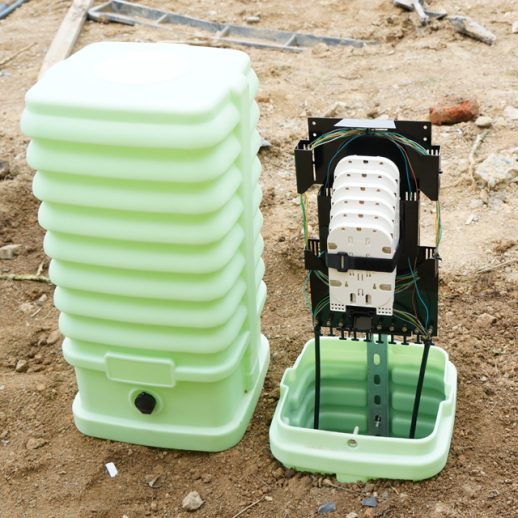
These instructions provide general information useful for pedestal installation to some common conditions that brings more connectivety to PON technology.
Site Preparation:
Ensure that national/local electrical and building codes, as well as OSHA and company safety work rules, are observed and provisions made for street flags, barricades, and cones. Secure permits as required by the city and company. Ensure the site is in non trafficable areas.
Excavation:
Measure the pedestal base from the bottom to the underside of the groundline mark of the pedestal base. Measure the diameter of the pedestal base. Excavate a hole with the depth you measured plus 4-6 inches, as well as the diameter plus 8 inches, to give 4 inches of room to work with on each side. Confirm the excavation floor is level.
Installation:
Tamp and level the floor of your excavated hole. Optionally, install the pedestal stake. Proceed to backfilling around the outside of the pedestal, tamping and leveling the earth once backfill is completed. Finally, fill the base of the pedestal with dry and clean gravels around the cable conduit.
Note: Base material shall be crushed rock 3/4” and smaller, and not “river rock” or“round stone.” Desired compaction and equivalent resistance to lateral loading will not be achieved with round stone. The rock should be free of soil and organic material.
3.
If necessary, remove the cassettes from the PON (Passive Optical Networks)insert. This is achieved by loosening the retaining screw’s on the right side of the cassettes and sliding the cassettes out from the rails on the left.
2. Cables to be installed can be secured to the bracket of the pedestal using zip ties or hose clamps. When attaching the cables to the back plate using zip ties, it is very important to not fully tighten the zip ties around the cable. Each zip tie should allow at least 1/8” of clearance on all sides. This is important as the cable will need to piston or freely move inside the zip tie independently from the pedestal in the case of ground
heave.
3. Route the fiber out around the outside of the PON insert.
After routing the fibers around the side of the PON insert, pass them through the back side of the bulkhead where the cassettes will be installed. Ensure that your cable goes around the outside of the back support on the right side.
Proceed to splicing your fiber into the Clearview Blue Cassettes. Note: Fibers must be spliced into the cassette in a LEFT EXIT configuration (exit is determined while looking from the back of the cassette)
After splicing is completed, pull the slack back through the pedestal and guide the cassettes up to their places on the PON insert. To install the cassettes back into the pedestal, engage the t-rails of the cassettes into place in their respective slide rails before securing the retaining screws.
Manage the cable slack around the two radius limiters below the PON insert
Install Splitters version 1
Loosen the strap at the top of the PON insert.
Place the ruggedized splitter inside the strap with the splitter legs facing towards the back of the pedestal. Secure the splitter body by tightening the strap.
Route the splitter legs around the radius limiters as shown.
Route the splitter legs down between the radius fingers on the front right side of the PON insert.
Bring the splitter staging plate up to the left staging area located at the base of the PON
insert. Place the push/pull plungers into the holes located at the staging area and push on the plunger to secure the staging plate to the bulkhead.
When making connections, remove connectors from the staging plate and route the splitter legs around the radius limiters on top of the pedestal as shown by the routing diagram. Different lengths of slack will be taken up depending upon the radius limiter chosen.
On the front of the bulkhead, route the splitter leg down on the outside of the radius fingers, turn up in between the radius fingers until reaching the desired row, then exit over the top of the radius finger to the right. Make the connection.
When installing additional Ruggedized Splitters, secure the splitter body on top of the previous one with the same strap. Route the fibers around the radius limiters on top of the PON insert and down the front right side of the bulkhead between the radius fingers.
Bring the staging plate to the open staging area on the bottom of the PON insert. Secure into place with the push/pull plungers.
Splice Only Configuration
The pedestal is capable of holding 128+ by adding up fiber trays to the metal supporter, one at a time to the included bracket.
Cables to be installed can be secured to the bracket of the pedestal using zip ties or hose clamps. When attaching the cables to the back plate using zip ties, it is very important to not fully tighten the zip ties around the cable. Each zip tie should allow at least 1/8” of clearance on all sides. This is important as the cable will need to piston or freely move inside the zip tie independently from the pedestal in the case of ground heave.
FiberKnct offers fiber pedestals and housing solutions that protect fiber optic,telecommunication and CATV networks, and brings more PON capacity and fiber droppings.